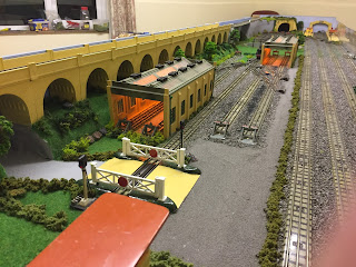
There were two primary reasons for extending the layout.
Reason one was due to the arrival of the trailer with more storage space but predominantly, the main reason was that work was ongoing to automate a single road level crossing, and there was no space in the current design to accommodate this.
This, like the turntable project has been kept away from this blog just in case it didn't work!
So I took a battered old level crossing and stripped it, drilling out the rivets from underneat that support the barrier hinges and posts. I then modified the barrier gates, adding in a support wire that could be connected to a pair of servos.
After lots of thinking about the best way to attach connecting wires, I decided to cut a slot along the bottom of each gate, drill a small hole further along and then attach the wire through the hole, bend at 90 degrees and run through the newly cut slot, bending again at 90 degrees in line with the original barrier lower supports (which were filed away) zooming in on the picture below, the gates (in unpainted form) modification can just about be seen.
The wires are in fact handrails from a scrap class 20 Bo-Bo!
Next job is to file away the lugs that form the latching mechanism. Previously the gate would have to be lifted slightly before opening and this will no longer be needed and could also jam the servo mechanism, so this was reamed away.
The original lower gate supports also needed to be drilled to allow the support wires to drop through to the underside of the base board where the servos will be mounted.
But there was too much free-play in the barrier, a support bush was needed. As we're recycling here, a couple of bushes from a scrap two rail chassis should do the job, just need to press them out of the wheels without damaging them...
Success!
Now this rather sorry looking crossing needs painting.
After stripping & primer, the beige coat is applied.
And left to dry.
This is then masked ready for the green edges to be applied.
Much tidier!
The gates were also repainted, along with the red reflectors in the middle.
Now painted, the modification is much harder to see, and almost invisible once installed!
The supports are refitted, these were originally riveted but this time I've gone with glue.
If you look very closely, you can just about see where the support wire protrudes through the bottom of the gate and is then folded flush.
The crossing then had to be supported to prevent damage to the wires. There was still some free-play in the barrier, so some heat shrink was added where the wire drops through the support bush. Again this can't be seen!
We're using the Arduino concept once again - this means writing another sketch and building a PCB with two trigger inputs and control of two servos and two signals. The basic idea is that as the single section where the crossing is installed is bi-directional, the circuit will detect the direction of travel, close the gates and then change the corresponding signal to green. Once the second sensor is triggered, the gates close and both signals are set to red. It's the same closure sequence irrespective of direction.
The signals will be mounted either side of the crossing.
Here the crossing is installed in the extension. The board has been drilled to allow the control wires to pass through to the underside of the board. In the distance, the points can just about be seen and it's from here that the first trigger sensor is connected, once again via the dead centre rails found in all HD points!
The second (east) sensor is in the points at the other side of the crossing.
The underside of the board.
The wires are bent again at 90 degrees as they appear from underneath, then another 90 degree bend into the servo arms. It was for this reason that the system couldn't be thoroughly tested prior to installation as we ran the risk of snapping the wires if they were bent & straightened too many times.
The two yellow buttons are manual overrides for the sensors, this allowed me to calibrate the position of both gates without having to run a test train up and down - carrying out adjustments while the board was on its side would have been very difficult as locos don't generally take well to being run on their side!
And after some final tweaks, it actually worked!
Another lengthy project that should provide some interest in the new extension. A quick nod to HD guru Ron Dodd, who recently posted a video of his crossing on his superb layout.
Video of the crossing operating for the first time, along with a compilation of the pictures above, can be seen here:


