
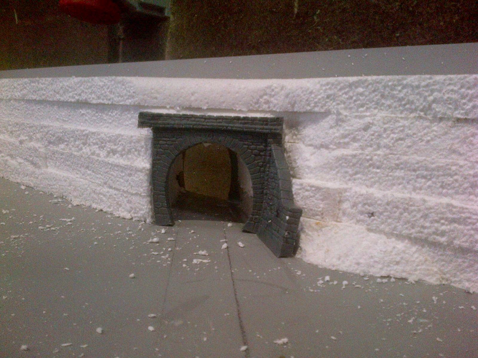
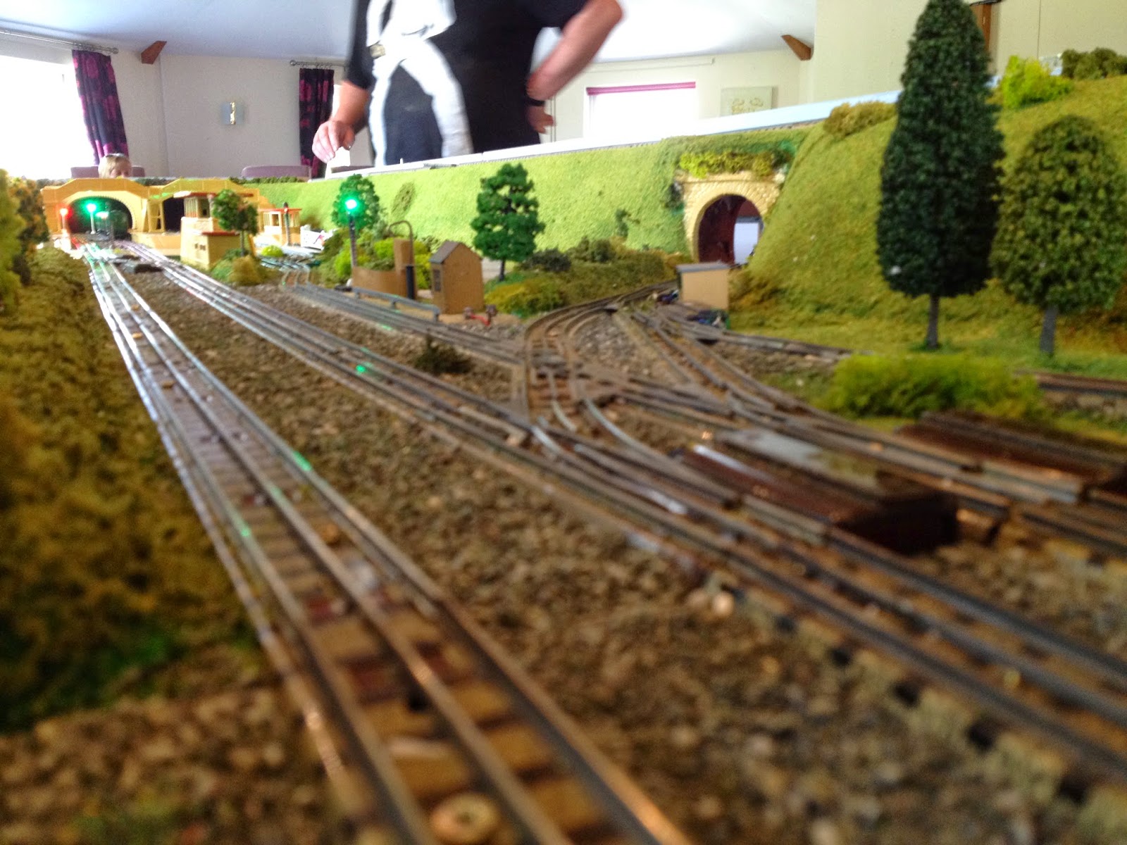
The two pairs of redundant points on the front of the layout have now been removed, with the half straights associated with the points also replaced in favour of full straights, the section has also been re-ballasted to match the rest of the layout.
Around the back, work to modify the rear of the upper loop has resulted in the rear sections being modified to accept the points before the straight sections, which not only extends the siding but eliminates the reverse curves at each end.
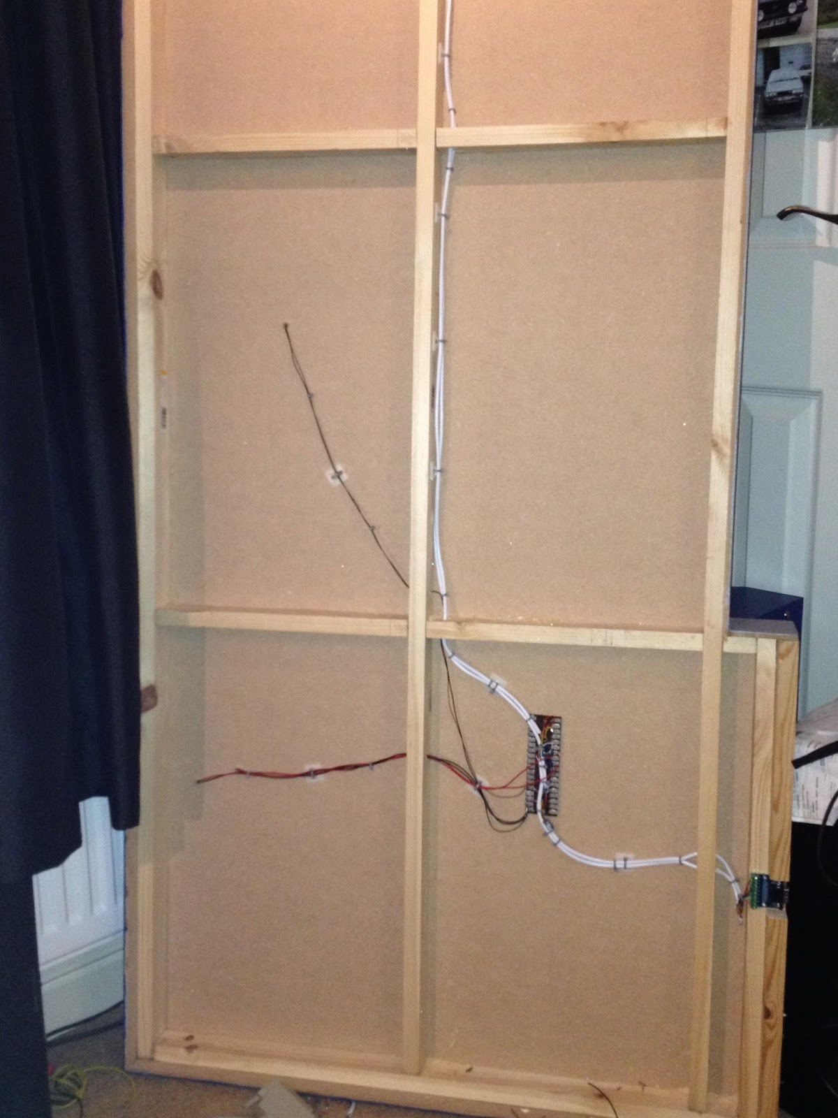
Work to renew the fiddle yard is progressing well, currently awaiting arrival of another 37 pin connector from Hong Kong and work has begun to revamp the control panel in readiness.
The original plan was to enlarge and then Photoshop the Scarm diagram and use this as the base for the control panel, sadly I don't have a copy of Photoshop and the basic Windows editing tools weren't powerful enough to produce a good enough image.
So using the Scarm diagram as a background image, I dug out the graphics files from when I originally designed the panel and drew the new layout over the top, essentially electronically tracing the image, this produced the overlay that I could stick to a freshly cut piece of perspex and then mark and drill the holes for all the switches and LEDs...

With everything carefully marked it was time for drilling, following by filing & sanding to remove all the plastic burrs. Fiddly but far easier than the aluminium I previously used.
I then cut the holes for the gauges...

This is the final result after drilling all the holes and applying the new graphics. The plan this time is to have the LEDs backlight the panel rather than protruding all the way through. I ordered flat top LEDs to achieve this, sadly the holes, although drilled at 3mm weren't quite large enough for the LEDs and in the course of enlarging some of the holes and fitting the LEDs into place, some of the overlay became damaged. I've now removed the stickers completely and once I have all the LEDs secured in place I'll print another set and then lacquer.

There's about 70 LEDs to solder into position this time so this wont be a quick or easy job. Thankfully by streamlining the design for the front of the layout, all of the redundant switches are recycled and the panel will have the same amount of switches as before.
I've also replaced the old Duette controllers with new Trax controllers, which are feedback controllers as recommended by HD guru, Ron Dodd. These should resolve the speed issues with the shuttle and also address the issues where some locos slow almost to a standstill on the corners.
I decided that the Trax panel mount controllers wouldn't look right in their new surroundings, so using the same technique that I used with the old H&M fascia, I removed the Trax fascia, scanned it at a high resolution and used the image to re-draw the lower control panel...

Slightly more tricky with these as the direction switch, potentiometer and two LEDs are all mounted directly to a PCB, so it was essential that everything lined up when I designed the panel and drilled the holes.
After much tweaking of the design, the new panel was finished...

The panel dropped straight into the box, replacing the old Duette panel. As much as I like the old Duettes, they are showing their age and although they give far better low speed loco control than the older A3 controllers, they just can't do low speed starting. Plus although fitted with overload devices, these are quite slow to react, the Trax version is almost instant.

Looking forward to seeing how these perform.


.JPG)
.JPG)
.JPG)
.JPG)
.JPG)
.JPG)


