Sunday 27 September 2015

Scrapheap challenge - part five - 2-6-4 tank

So this is the loco that I fully expected to scrap!

At first glance, this looks bad...


But actually it isn't. In fact, as well as being only damaged on one side, the problem here is being caused by one missing connection pin.

My first attempt was to replace the pin by extracting one from a spare, damaged valve gear set.

To give some idea of how fiddly this job is, the connecting rod and pin are below, bear in mind that this picture was taken using a magnifying glass!


It turned out to be beyond my ability to repair but still it seems a shame to break this up. So another experiment was tried using a piece of wire, passed through the rods, soldered at each end and then cut back. All done using the magnifier. Pretty intricate stuff!


And this is the result!

The old armature looks pretty fried and as I already had a brand new spare (ordered in error for the 0-6-2) I didn't even bother checking it with the test meter. After checking the resistance of the brush tubes and lubricating as normal, I fitted the armature and a neo magnet. 

And it seems to run.

A nice, unexpected save. I have a spare GWR body that was removed when I was doing the home-made transfers, so once I've painted the end of the valve gear I'll fit the spare body.

This may well end up being the first of the four to be completed, whereas it was expected to be the only one scrapped.

Result!!!

Scrapheap challenge - part four

I decided to make another red LMS tank, so after masking the bits that need to remain black, two coats of red were applied...


This one is about to become 2273, using leftover transfers...


There were two final LMS decals remaining and enough numbers...


The Fox transfers are water slide, and quite forgiving...


My previous effort was used as a guide to ensure everything was straight...


Then the numbers are applied in the same way...


Final check down the side of the body to make sure everything is in line...


Then the transfers for the other side are wetted ready for application...


And applied...


With the front and rear buffer beams painted red, the handrails are re-attached. Just need to add the smoke box numbers at some point...


Ordered a replacement armature but ordered the wrong one, so I have a spare armature for a 2-6-4.

Total cost of restoration of this loco, technically is still nothing!


Wednesday 16 September 2015

Scrapheap challenge - part three - 0-6-2 tank

A replacement armature is on its way, so I decided to start work on the body.

This is one of the worst bodies I've ever seen...


And the other side isn't much better,,,


The only option is to go back to bare metal. No need for an overnight stay in a bag of oven cleaner, a quick bath in caustic soda removed most of the paint, and some final sanding removed the rest.


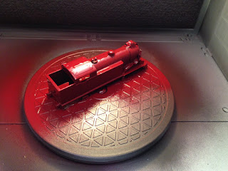
I now have a spray booth, using the turntable makes the painting job much easier. Primer first...


Then two coats of black. Already it's a huge transformation...


The question now is what to do with it? I already have eight 0-6-2 tanks and already have 69567 /8 /9 - I neither want or really need a 69566 or 69570!

Looking at the other locos in the box, the one I like the most is the recent maroon LMS that I made using Fox transfers. As the process for adding the red involves using a black base it will be a simple task of masking the black paint and adding the red. There are enough transfers leftover to make a running-mate.

By the time I've finished the paintwork hopefully the armature will have arrived and the first of my freebies will be in service.


Monday 14 September 2015

Scrapheap challenge - part two


I've now had a good look at all four of the locos acquired last week...

2-6-4 Tank: Valve gear damaged on both sides & linkage missing. Currently I don't have any spares to repair this one. Highly likely that this one will be broken up for further spares unless valve gear can be replaced. Body fixing, valve gear, bogie & pony screws all missing.

0-6-2 Tank: Mechanism seized, no magnet strength. Loco stripped and lubricated, neo magnet fitted. Found armature resistance of 1 ohm across each segment. Rewound armature needed to finish mechanical work. Body requires complete respray, colour & operating company TBC.

Bristol Castle: Brush arm missing completely, wires snapped. Armature will be tested once replacement brush arms can be located (I have spares somewhere) Body requires complete respray. most likely will remain GWR green but renamed. Body & tender screws missing.

Duchess of Montrose: Axles stiff, no magnetic strength, armature commutator segments excessively dirty / greasy, rear pony missing, front bogie missing. Armature removed and cleaned, replacement bogie & pony found, neo magnet installed, axles lubricated. Mechanically restoration complete but body requires stripping to bare metal. Will probably be repainted as Duchess of Abercorn (later Wrenn model) using grey paint.

So basically three out of the four are likely to see life again.


Sunday 13 September 2015

Scrapheap challenge - part one

Quite why anyone would just throw this little lot in the skip is beyond me!

After a receiving a quick answerphone message, this little box of unwanted "bits" arrived for me to look over. Needless to say I wont be throwing anything away here.


I will fully PAT test the Duette controller before I run it but early signs are that it's in full working order. The track is dirty but straight and can be revived, as can some of the coaches and wagons.

The four locos I have confirmed are all non-runners, with only the Duchess of Montrose showing any signs of life at all - the wheels just about turn.

The valve gear of the 2-6-4 is damaged and may be beyond salvation. Hopefully I can find something in the spares box to bring this one back to life. I think I can certainly get the other three running but they will all require repainting.


A job for the winter I think and some more Neverwas loco projects to come...

Thursday 10 September 2015

More layout mods - part three

Time to begin wiring the additions to the layout.

The electronic uncoupler was obviously very easy to connect up and works as expected.

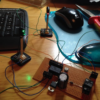
Next came the dual signal aspect control, based on the same principal as the one installed some months ago at the other end of the station but utilising the power from the points relay to determine which aspect operates through the delay circuit. A video would demonstrate this better but the circuit board is below:


As with all my electrical projects, I bench-tested for correct operation before installing...


It works perfectly and I will capture some video footage of this when the layout is next in use.

Next it was time to install the second semaphore and wire it in sequence with the existing one. Bascially I have a single home signal at one end of the layout with the intention of adding a dual home and distant signal after the TPO, with the distant signal wired to activate with its home signal as the train passes and then the distant signal would return to green once the other home signal has reset (does that make sense?!)

The system for operating a semaphore is different to the colour signals in that we need a pulse power feed rather than a constant power supply. To achieve this I produced a timing circuit with additional capacitors to operate in the same way as the points, ie when power is applied, it travels through the capacitor until charged, which basically means a pulse feed is sent through one coil and when the power is cut, the capacitor discharges through the other coil. This works well on the points and also works well if powering one signal.


However there is one flaw with the design - the ground connection is not wired to the common terminal, it goes on one of the coil connections. With the dual signal there are four feeds and only one common, bascially it means that I can't get the signal to operate using the same circuit.

After more trawling of the internet I managed to find a schematic for a dual capacitor discharge circuit, so I removed the existing one from the board, added the extra capacitors and made the relevant wiring changes. The schematic diagram assumed the use of a DPDT switch, so in theory the relay would operate in the same way, right?

Wrong!

What I had basically just unwittingly constructed, via the 25v 4700uf capacitors was a rather large 25v power supply. The relay coils, being of 12v rating, couldnt cope with the power being sent through the coils and while one survived, the other fried!

So after more head-scratching I realised that what I needed, and what the schematic really should have included, was diodes - two for each charging circuit to stop the voltage feeding back through the relays. After more checking with the multi meter I was able to confirm that the capacitors were then charging properly and thus, the dual signal then operated perfectly, with a nice, positive "clunk". Thankfully my old marshall power supply also survived being back-fed with 25 volts!

The final circuit, while not the prettiest I've ever constructed, is below and will be fitted to the underside of the board shortly...


It's worth pointing out to anyone wishing to play with capacitors that they must be treated with respect, and remember to always discharge them. Normally grounding them is sufficient but to be honest, grounding four capacitors together that were all fully charged, isn't for the faint-hearted, or weak-hearted.

But the bang and the sparks were pretty impressive!

Monday 7 September 2015

More layout mods - part two

More progress since the last update...


The two workmen have been busy! 


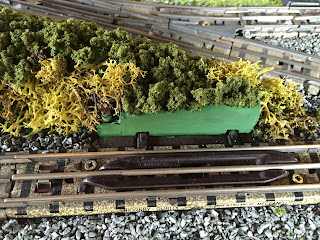
A new bank has been added, using polystyrene, modrock and moss. The solenoid of the uncoupler is hard to camouflage but by painting the casing green (after I'd lovingly sprayed it black!) and hiding most of it within the scenery, it blends in rather well...


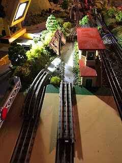
Only a week since the last pictures were taken, you would never know that there was ever an additional rail, two pairs of points or a diamond crossover here!


Although it's a shame to lose the complicated (but smart looking) track arrangement, the changes here should make a big difference to the reliability of the layout. This was by far the weakest part of the whole layout.


The stone-work at the back of the turntable sidings has been stripped back, treated with PVA and repainted, no more cracks or flaky bits!


And some coal added for extra realism!


I take no credit for any of the scenery work seen here. My job is to rewire underneath and add the automatic signal sequencers work has already begun on this)


Saturday 5 September 2015

Trix Western

Although I've never really encountered these in real life, I've wanted a Western for some time.

The closest I'd come so far was when I purchased a job-lot of re-worked Bo-Bo & Co-Co chassis that had been modified to accommodate Trix Western & Warship bodies. Sadly they were held in position using blu-tac and didn't look good enough to show, so the chassis and motor components were slowly recycled and have been put to good use over the years, allowing me to convert the Brighton Belle and several SR EMUs to three rail operation using the leftover wheels, and several Co-Co restorations, most recently the St Paddy, using the spare motor bogie.

So when this Trix Western appeared on Ebay, I snapped it up for the reasonable sum of £30. 


My knowledge of Trix is limited but I am aware of their Trix Twin three rail system, which although looks similar to HD allows independant operation of two trains on the same track. As this model was produced in both two and three rail versions. logically there would be room under the axles for a third rail pick-up!

Dismantling was dead easy, both powered and non-powered bogies, complete with housings are prised from the plastic body. No remedial work required on the motor itself, it's in good condition and even both lights work.


Although I originally planned to install a genuine HD pick-up assembly, the clearance underneath looked too tight, also there is a large weight that sits above the non-powered bogie, which would be difficult to reinstall and will be required to counteract the resistance of the pick-up. So I went with the Marklin skate instead (plus it can be mounted with one small screw!)


A relatively easy conversion that's now happily running around the loft test track.

Wednesday 2 September 2015

More layout mods - part one

We celebrated the first anniversary of completing the layout... by taking bits of it apart!

After much consideration, I decided that the last remaining diamond crossover had to go. The crossover was causing some rolling stock to jump when passing over it and some derailments / uncouplings. Also due to the complex layout at this junction there was quite a kink in the tracks.

I'm not a fan of diamond crossovers, I own half a dozen and when this layout was designed, I reluctantly incorporated three of them into the design. Following the recent modifications to the rear fiddle yard, this left just the one crossover at the front for the run-around loop. In reality after a year of using the layout, we've never used the run-around and it's unlikely that we ever will. I find myself manually detaching locos on the inner loop, running forwards over the points and then reversing into the turntable sidings to swap locos, so the void left by the crossover is being filled by an electric uncoupler. The extra points involved in the run-around loop also creates issues when running tender-first out of the turntable, there are frequent derailments over the second set, so changing these to a half curve should eliminate this problem also.

To do this job properly, boards one and two needed to be set up and joined together properly to ensure that the tracks stay aligned across the board joins.

First job was to start lifting the tracks...


On a non-scenic layout, this would have been dead easy, not so when there's ballast involved.
(The two workmen actually now look like they're doing something!)


With the tracks lifted, I also needed access to the points on the inner loop. A second semaphore signal is being installed so I need another electric trigger. The points have a ready-made dead section that makes this really easy to do.

In the foreground of this picture you can see a piece of wood that was added to compensate for the warping that occurred during the initial build of the layout, this lifted the track sufficiently enough to make it level.


And while butchering the tracks on this board, it made sense to fit another set of triggers to the points at the end of the level crossing, these will provide automation to the two colour light signals, meaning that all the signals on the layout will be automated.


Second pair of points gone, half curve installed and track refitted...


The new, streamlined appearance...


Some tidying and ballasting to be done, which is not my department!


Looking down the layout, the track is now much straighter than before, which should improve reliability even further...


The second semaphore to appear on the layout. The plan is to automate the home and distant signals using the existing semaphore and the newly installed trigger. As the train passes over the points, the electric current generated will operate a capacitor discharge based timing circuit, this will throw both signals to red at the same time. Once the timing circuit has finished (the capacitor has discharged) the home signal will then revert to green, with the distant signal reverting to green once the next trigger circuit, fitted after the other semaphore, finishes its cycle.

That's the theory anyway.


Also due for some attention, the scenery along the back of the turntable yard. The paint and PVA has flaked quite badly so has been patched ready for repainting.


Once the ballast has been laid and dried, the next job will be to flip the board and rewire underneath, removing all the redundant points wiring and installing the timer circuits for the signal controls.

More to follow...