Wednesday, 29 July 2015

St Paddy & Atholl repairs

At the Bridport exhibition, two locos failed. Sadly they were also two of the locos that have been worked on recently!

St Paddy arrived earlier this year, minus a bogie but during its first outing in Yeovil it was found to be seriously down on power. Such was my desperation to see it run, I swapped the chassis with the green deltic, and then never swapped it back. So technically it's the green deltic that's faulty and not this one.

Initial thoughts were that this was a simple wiring fault as it showed no sign of life and no current consumption. In reality the wiring was probably the only thing that was actually alright.

Once stripped and checked on the bench, I had to resolve the following:
  • Stuck carbon brush
  • Dirt / grease build up on armature commutator segments
  • Excessive carbon between commutator segments
  • Brush tube too far away for carbon brush to make contact with armature
  • Bottom armature bearing spinning in cast
  • Tyre missing
The lower bearing was glued back into position, there doesn't seem to be much movement with the armature in position and does explain the alarming clattering noise that this chassis has always made!

The other faults were fixed relatively quickly and the loco has now been returned to the stock box ready for the next show.


Atholl was more of a challenge. It was a real disappointment that this one wouldn't run properly and with current consumption of 0.75 amps, this is far too high and would only lead to the inevitable burnt out armature if left. This is the beauty of having ammeters installed on the layout - it can alert you to problems before they become major issues. It's also handy when using feedback controllers as I do, as the controllers tend to increase the power when needed and can hide issues such as these.

With the body removed, I took out the armature and found nothing wrong with it. The problem was with the valve gear and connecting rods - too much rolling resistance and not easy to turn by hand, that explains the high current consumption. I'd previously had issues when I refitted everything to this loco with the rod pins falling out. I'd removed all the valve gear when I painted the front assembly. Under better light it became clear that I wasn't the first person to have removed the valve gear and traces of glue could be seen around the holes of the rod pins. The pins themselves appear to be fine, some of the holes however are more oval-shaped. Presently I have no real way to repair this and I'm not keen to glue it.

I decided to do a chassis swap. I have a Duchess of Sutherland, a loco that was sold as a poor repaint but at the time, when running on the old layout, actually looked quite decent. Recently it's been omitted from the stock box so I removed its body and rather than removing the valve gear and risk introducing the same problem, I simply rubbed-down in-situ and hand painted the ends. 

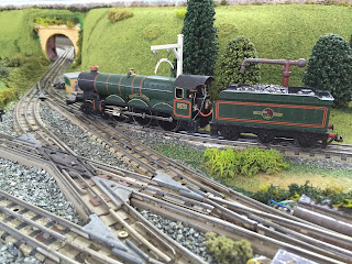
Both locos are now ready to run as per the picture above... Result!

Bo-Bo restoration

I own three class 20 Bo-Bo diesel locos.

All three are normally taken to exhibitions but in reality they don't see much use. In fact the blue, Wrenn-bodied class 20 sees the most use as it's in the best condition.

One of the three locos is deliberately fitted with the magnet reversed so that they can be run double-headed and nose-to-nose as they would in real life. However a good looking layout deserves good looking rolling stock, hence my attempts at home-made restorations, transfers and overlays.

The two original HD Bo-Bo's are looking tired and very scruffy. Time to try some DIY restoration. I'm not too worried about messing this up - there are plenty of these still available and they're not expensive so I had no issues or concerns with stripping the body off this Bo-Bo...


One screw is all that holds the body in place, it then lifts off. The handrails and ladder are also easily removed by bending the clips inside the body.

The green bodywork is fine. It looks as though the only paintwork is the grey of the base and roof, the green seems to be in the plastic injection moulding itself, and thus is in very good condition.


After light sanding, I used the same, pin-stripe vinyl masking tape as used on the Atholl project. This stuff is really easy to work with and is easy to peel off. The body was masked along the line of the handrail, this means that if my line isn't perfectly straight, the handrail, once refitted, will hide it!

With the edges masked, standard masking tape was used to mask off the rest of the green bodywork and front & rear buffers.


I'm using the same grey Halfords primer as used for the EMU coach roofs and wagon roofs. It is a different shade to the original but the Bo-Bo will most likely see use hauling the refurbished wagons, so the colour of all the roofs will be the same!

Two coats of primer applied in quick succession (these dried very quickly in the warm loft!)


I removed the masking while the paint was still drying, this seems to avoid damaging the paintwork. I then gave the whole body a dusting of matt lacquer. This really tidied up the finish of the green body...


The buffers are in reasonable condition so no point repainting them. The handrails were refitted once everything had dried.

Looking at the time stamps on these pictures, from the first picture to the last, this was achieved in less than an hour (apart from refitting the handrails) and makes a massive difference to the appearance of the loco. 

Once the other Bo-Bo has had the same treatment I'll be more than happy to see these running around the layout nose-to-nose.

Total cost of restoration: NOTHING!


Tuesday, 28 July 2015

Yet more modifications

The layout's now attended four public exhibitions and the more we use it, the more we learn about what works well and what doesn't. It's still not been a year since the layout was declared finished and already there have been extensive modifications to improve reliability and ease of operation.

The main area of focus this time is with the run around loop and its connection into the two main running loops. Both loops can currently access the run around but in reality, the outer loop access has never been used and is unlikely to ever be used. With steam loco operation confined entirely to the inner loop, no steam locos ever cross to the outer loop, which is almost exclusively used for the multiple units, diesel & electric locos and long goods trains. 


The diamond crossing is now the sole crossover. It's fair to say that I'm not a fan of them. This layout originated with three of them and the previous layout had its fair share of them, most of them being removed due to various issues. It's been found that some, but not all of the rolling stock tends to jump as it passes over the crossing. The other issue is that when running tender first out of the turntable, two pairs of points have to be traversed, some locos tend to stall, some don't like tender first running at all and derail. 

Much as I love the design of this junction, and the track had to be cut & modified to fit, in reality it would be easier to remove the outer loop crossing and leave just the inner access. The second pair of points can be replaced with a half curve which will make loco movements much smoother. We do frequently uncouple a loco and swap over via the points and turntable, so an electric uncoupler, as well as being really useful here, will also drop straight into the space where the diamond crossing currently resides.

Some creative ballasting and landscaping will also be required to hide this lot.

While the tracks are being lifted I'll also install another semaphore signal trigger. These work really well and the automatic signals look fantastic!

Although it's a shame to be removing items of interest like this, overall it greatly improves reliability and helps us to keep things running.


Sunday, 26 July 2015

Website address

Having attended a number of exhibitions this year, and with four more to attend before the end of 2015, we're directing more and more people to this blog and its content. Trouble is, I can never remember the exact website address!

Today and for the first time ever, this site has had over 100 hits, so it's time to simplify things and improve the access.

I've purchased the domain "dublonutz.co.uk" and set it to automatically redirect to here. I see no need to host the content of the site elsewhere at the moment.

www.dublonutz.co.uk

Saturday, 25 July 2015

Bridport - Best in show!


Our first silverware!

The attendees of the Bridport Model Railway exhibition voted our layout best in show. This is only our fourth public exhibition so it's great to receive some recognition. I've never owned a trophy before!

After a wet Friday evening setup (we've never setup in the rain before!) there were many electrical gremlins - more so than ever before. I'd done extensive work to the fiddle yard to install additional track isolators and four more electric points (as previously mentioned) and unfortunately, even though I documented all the wiring changes, this was the first time that the three rear sections could be connected together. There just isn't room at home to test them all, and along with some track shorts, there were many things that didn't work... and still don't!

Thankfully the issues were confined to the rear of the layout and didn't detract from the running of the four main lines, once again we kept things running all day and many attendees commented on this achievement. People like to see things running and this was my primary goal when I first envisaged the new layout.

No video footage was taken this time, as the basic design of the layout hasn't changed. Just a chance to run my new additions, repaints, re-transfers etc. It's only been two months since the last outing but there was much to test.

After stripping and repainting my Duchess of Atholl, it was very reluctant to move, this one will require further work to find out why. Disappointing as it was a good runner until I took it apart. Deltic St Paddy also refused to move, I suspect a broken wire and will repair shortly.

Regular readers of this blog will be aware of my obsession with double-heading. One of my greatest frustrations to date has been the inability to double-head my two Castle locos. The front bogie has no front coupling, or any space to install one. I've tried several ways to join the two locos together (including chaining them together) with no success. After locating a spare front bogie in the spares box, I dediced to experiment and reamed a portion of the front of the bogie, then drilled a small hole and installed a coupling and rivet from a scrap wagon. After testing the Castles to see which was the fastest of the pair (fastest loco always goes first) I swapped the bogies and the results were really impressive!

The refurbished (with overlays) plank wagons got their first run, and the first time a goods train has appeared on the inner loop. A nice addition to the layout.

The thirty refurbished wagons also made their maiden voyage. A little hard to pull and had to be reduced in length. I'll do some more investigation to see why they were so reluctant to run but those that did run looked really good!

The two recently repainted 0-6-2 tank engines made their first appearance on the shuttle, displacing the previous refurbs. These ran faultlessly all day and were a relatively good power match. They make my first attempts at loco repainting look rather poor in comparison.

Finally, and I make no apologies for the copious amounts of EMU shots, the new, six car (2 x 3 car) SR EMU, after some initial stuttering and hesitation, made a fantastic debut, purring around the layout as it always did but now with more coaches. The rear three cars are not powered, a first for me as I don't like using unpowered dummies but there's ample power in the motor coach and I can't justify the expense of  another power car, especially one that's in good condition.

Lots of pictures below, enjoy!


Sunday, 19 July 2015

Post number 1

The first ever post on this blog has now been updated slightly.

Time out

Having returned from a week's holiday, it's back to work and time to prepare for our next outing on the 25th July.

I acquired two more wagons, one is in very good condition so it will be left alone.

The other wagon I decided to pay homage to our local model railway club!


With work on the blue EMU completed, I now also have a fully functioning green EMU to partner it. Currently both sets are powered having converted the recent acquisition to three rail running so I'll test the two units together next weekend to see how they perform together.

I had a go at repairing one of the old cab front ends, this was the one with a corner piece missing. It's not perfect but it's perfectly usable:


And finally, with less than six days until the next public outing, these ideally need to be installed in one of the rear boards. Most of the board wiring is in place already, it just needs some time and a few more holes drilled.


This will allow us to run trains from the turntable, through the back of the layout and into the storage sidings at the back.

(If I get time to fit them)


Thursday, 2 July 2015

More layout modifications

When first designed, the electrical connections were provided by one single 37 pin cable, which connected to the first front board, with male & female connectors between each board and the rear sections were connected via 9 pin connectors, due to the fact that there was only track power being transferred from front to back. When designed, it was envisaged that the layout would be operated from behind and it was pointless having electric points if the manual ones were within reach.

The idea of running from behind was binned on the first outing - the height of the layout, coupled with the back scenery meant that it was impossible to see anything at the front. So the layout quickly became side-operated (which is actually far better) and the fiddle yard was modified due to issues with all the reverse curves and crossovers, so electric points started creeping in to the rear boards, which required further electrical modifications. Nothing too major, to get the additional power all I needed to do was install a double 37 pin connector in the rear, power was still supplied from the control panel via one lead but now plugged into the rear board first, with the original lead plugging in from the rear to the front.

The wiring design I used for the points control mechanisms means that whereas if I'd used a CDU mounted in the panel, I'd need two wires to control each set of points, my system uses only one wire for each, these go to relay PCBs that I've built and installed in the boards and a simple on/off switch opens and closes the points as required, saving on wiring and space within the 37 pin connectors.

As we continue to use the layout, we learn what runs well and what doesn't, what areas could be improved etc. The new fiddle yard layout is a vast improvement on the previous design but the only downside is that the sidings are very long, storing something like a five car Brighton Belle wastes lots of storage, so it would be handy to install isolated sections to allow parking of two complete trains. This is where the DCC system - if it had been more successful - would have been of benefit as it allows multiple locos to be parked on the same track section.

It would also be handy to install more electric points at the end of the fiddle yard, we run locos from the turntable sidings, through the turntable and into the fiddle yard, so the ability to control the rear sidings that connect to this at the back would be of benefit.

So to install eight isolated track sections and three more points means that I need to add eleven more wires and switches from the panel, and the 37 pin connectors don't have enough spare capacity. So a solution is required.

I've had to install a second 37 pin connector block in the control panel...


The original connector will now power the front three boards, the second will work the rear section. No additional connection leads required, the front section will now plug directly into here rather than into the rear board.

Thankfully I kept a wiring diagram and pin configuration list, so it was a reasonably easy task to identify which wires in the original connector needed to be swapped to the rear. 

The control PCBs for the track isolation and additional points motors have already been made, just waiting for some more switches to arrive.

There are now more electronics involved in the fiddle yard than in the front of the layout!