Wednesday, 18 February 2015

Idle hands...

For the first time in over a year, I have very little to do.

It's not uncommon after a two day session to come home with a loco or two in need of TLC but once again this time there were no casualties.

I'll need to investigate a small issue with the LED signals which should just involve swapping the polarity and I need to modify two more electric points for spares but that's roughly an evening's work to complete both tasks.

I need another project! - I don't have sufficient spare track (or the funds) to rebuild in the loft and now that the new layout is finished and being shown multiple times during the year, I have ample opportunity to play trains, so a loft layout might not actually be needed, aside from a small test track maybe. Plus the extremes of temperature and the lightweight construction of my loft means that time spent up there would be limited and not terribly kind to the rolling stock.

So I've started searching for locos again and then reminded myself of the HD 0-6-0 tank that I bought ages ago and stripped. I managed to locate most of the parts from when I dismantled it, sorting the motor was easy with just a quick lube and a new magnet but now I have the challenge of three-railing it.


This particular loco was produced towards the end of Hornby Dublo construction and was only manufactured as a two rail model. The half inch motor was used on other locos, such as the 8F but the challenge here is that there are only three axles and the motor drive is taken from the centre axle - not a problem for two rail but for three rail, that's where the pick-up skate would go, there's a bloomin' big worm cog in the way. Then there's the space between the chassis and the motor assembly - there is little or no room to bolt through the pick-up assembly. A Marklin skate also wont fit.

If possible, and for the best running, I want proper HD pick-ups under here. I could use brass fasteners but these tend to require constant adjustment and as I intend to use this on the shuttle, the frequent travelling over the points will mean lots of adjustment - I've already had bitter experience of a Bachmann 2EPB pole-vaulting itself off the layout when the brass fastener dug itself into a gap in the third rail and that's not something that I'm keen to repeat.

I'm going to attempt to use the individual pick-up assemblies found under the Deltic, one either side of the main drive cog. I now probably need to ream the underside to accommodate and then work out a way to secure the pick-ups into position.

The reaming tool was last used for the Brighton Belle project and although initially I was unhappy with the way it ran, it has settled in quite nicely and now runs without issue.

This one I think will keep me busy for a while...


Sunday, 15 February 2015

Train Cam returns!

After finishing all the modifications, I filmed the layout again.

This time I remembered to capture the upper loop and turntable sidings and filmed in blocks so that there was some traffic flowing.

As the camera is fixed directly to the chassis (no body) of a 0-6-2 shunter (which needs some mechanical TLC) there is a fair amount of clatter.

So turn the volume down, and enjoy...

https://www.youtube.com/watch?v=lOcjM5b2ywc

Weekend run completed

 Another weekend of hard work.

What would normally be two days of playing trains was in reality one day of solid work and one day of playing trains!

After making some minor repairs to parts of the layout, it was time to link the three recently modified boards together for the first time and begin aligning the tracks. Some warpage has occurred and there were difficulties getting the front and rear sections to align. Some minor issues with two of the newly added points, which considering there are now 17 more pairs of electric points, some issues were expected.


Finally completed the electrical work to the turntable sidings - the isolators to allow parking two locos on each track were added when the layout was built but this part was never wired. After building a new relay control circuit, all of these isolators operate from one switch. And it works rather well!


The rear straight section of the upper loop warped badly over the winter so has been replaced with a new, dual layered plywood section. This was also replaced again after I measured the old one wrong!

We've also removed most of the old wooden supports and replaced with adjustable kitchen legs, which will allow better flexibility and height adjustment in future. The combination of these two modifications resulted in much smoother running.

The main lines now run through the centre of the fiddle yard and now complete trains, even the long goods train, can be driven into and out of the sidings and stored without issue and there's still enough space to store all the locos.

The E3002 electric loco, now completely modified and sporting a proper HD pick-up assembly, can be seen. Although it's a very smooth runner, the loco is only driven via one axle and struggled with the tight radius inner curves, the side frames also protrude so far that they were hitting the signals so I've removed them and stored them safely. As the outer loop is predominantly diesel and electric, it fits in really well.


On the inner (steam) loop, access to and from the turntable is now much smoother and easier to operate and whole trains can again be parked up.


The long goods train just about fits and even Brighton Belle, which of course isn't genuine HD or three rail, manages to negotiate the pointwork at either end.


Upper rear section now looking much straighter than before...


The new design incorporates some handy siding space for the diesel locos...


Viewed from the running rails, the new fiddle yard fans out from the centre via the standard HD points, into the modified ones...


And after all that work on the signal aspect controllers, I fitted one as a tester, to the far signal in this picture at the end of the main station. It worked exactly as expected and almost exactly as my Ipad simulator predicted. Next project will be to install them to the remaining signals. 


A successful weekend with no loco casualties. We're now ready for some 2015 exhibitions!

I managed to bring the video camera this time. With over 50 video files and nearly 5GB of footage, it will take a while to edit and upload.

Keep an eye on YouTube...


Thursday, 12 February 2015

Spoons

I've had occasional problems with some locos stalling over points.

Having researched further, it appears that the problem may be down to excessive wear on the pick-up shoes, or spoons as they're sometimes referred to.

The problem seems to be more so with the 0-6-2 tank engines, even though the pick-up skate is the same length as the standard locos, although it does tend to overhang slightly at one end which appears to be a design problem.

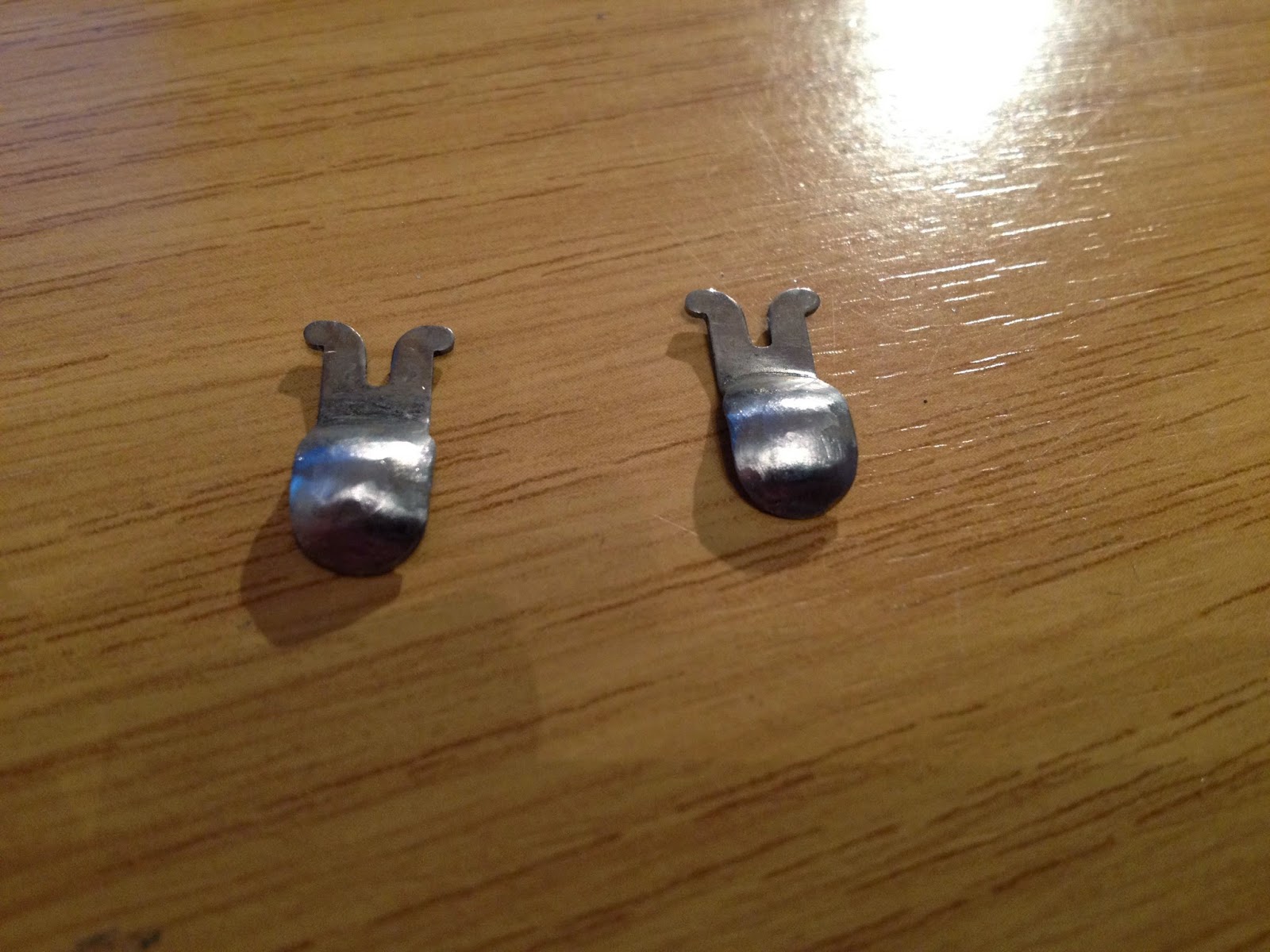
Having double-checked the pick-up spoons, a number were grooved quite badly so I've sourced some reproduction ones and replaced the worst looking ones, however I've also read that others have attempted to re-profile the old ones using solder, so I decided to test this for myself.

Of the three pairs of spoons below, the top left are the new, reproduction ones sourced recently. Top right is a pair that I previously experimented with, and the bottom pair are the two that were in the worst condition, the groove is clearly visible:


First job was to clean up the spoons, removing all dirt & grime ready for soldering:


Once cleaned, I applied heat from the soldering iron, then applied the solder:


Waiting for the solder to cool:


Once cooled, this is the result:


Now for some grinding:


And a final polish:


The solder will probably be much softer so these may require work again in future. I'll test them shortly.

Wednesday, 11 February 2015

Fiddle yard finished

This weekend sees the layout in action for a private two day session. This will be a chance to assemble the fiddle yard and align the tracks properly, while undertaking some other minor repairs & modifications.

All of the electric points and their control circuits are now in position, this presented a fair bit of additional wiring as can be seen below:


With the two end boards done, I then modified the tracks on the centre board. As expected this was reasonably easy as seven of the tracks were left in-situ from the previous design. The points that link the front and rear centre sections have been relocated to the end board, so the trackwork here has been changed to a simple straight and half curve, I drew around the old points before removing them so hopefully this will still line up. 


It's impossible to link the boards together at home but hopefully if I've done my planning properly, most of the tracks will line up and it shouldn't be too big a job to sort the rest.

While I'm working on the front boards, I intend to fit my signal aspect controls, which are now finished. The one here is designed to work two signals which protect one pair of points (one is red, one is green and the aspects swap as the points change)


The circuit is the same as the one designed in the previous post, with a trigger relay operated by the train movement charging the capacitor. The only addition is the 2K ohm variable resistor wired in series with the original resistor, this allows me to adjust the timing. With a 2200uF capacitor the times are between 15 and 30 seconds, with the larger 4700uF capacitor on one of the other boards, the timing can be adjusted between approx 20 and 60 seconds. This one will be fitted on the outer loop where I tend to run the goods train, which takes a while to fully clear the signal.

More pictures and videos to follow.

Saturday, 31 January 2015

Automated signal schematics

After my initial success with the basic signal control circuit, I needed a second to work the two signals at the other end of the station. As with most of the signals on the layout at the moment (apart from the two automatic ones on the shuttle) their aspect control is governed by the routing of the points, ie when the points are changed, the corresponding signal also changes and I want this feature to remain.

The design of the new circuit means I can wire it into the existing wiring and simply divert the current signal feed wires into the PCB. I've also designed a configuration for working a pair of signals from one control PCB.

After some head-scratching around how to configure the circuit, I acquired a circuit design tool for my Ipad, which also allows me to run animated simulations of how the circuit will perform - changing the values of the capacitor and resistor shows pretty accurately how long the timing will last. I might splash out on some variable resistors so that I'll have the ability to adjust the timings. It still works out cheaper than buying them pre-made!

Using the design tool, I've mapped out the schematic diagram for a two aspect signal as per below...


For the circuit to work, I need a trigger signal to start the timing (charging / discharging) process. For nearly all DC applications, either reed switches or infra-red detectors are used. Neither of these options appeal and for three rail applications there is a much easier way, which uses the dead track sections in standard HD points, which is why there's a second relay in the circuit.

The left-hand relay is momentarily energised by the passing train, this closes the relay contact and allows voltage through the diode into the capacitor to charge it. Once the train has passed the section, the coil is de-energised, the switch contact opens and the discharging process begins. Current now flows from the capacitor, through the resistor to the base of the transistor fitted in the 0v return of the main control relay, which is powered with a permanent 12v supply. The transistor is now energised via the capacitor charge voltage in its base so the relay coil is now powered. The contacts change and power is sent to the red signal (colours not shown here) once the capacitor has fully discharged, the transistor loses its base signal and prevents current flow, de-energising the relay and returning the contact to the green (normally closed contact) position.

The switch shown on the right of the diagram is the red or green power feed that is received from the existing wiring configuration. When the signal is set to red, power is sent via the other diode straight to the red signal, bypassing the relay control altogether.

After even more head-scratching, I worked out the circuit for two signals, controlled by the same signal feeds (red and green aspects swap according to the points position)


I'll be relying on the track voltage from the running train to provide the power to the coil of the first relay, I know from previous experience that this will work. I don't need to add any isolated track sections, I can use the dead sections of the points (circled)

The two short dead sections circled have wires soldered underneath which will feed into the first relay coil. Two additional diodes will prevent track shorts from occurring. Thankfully when we built the layout, I soldered extra wires on all the points as a precaution!


Here's a quick mock-up using a three rail pick-up from a three rail loco to demonstrate how this works...


As the locomotive approaches this section, the third rail pick-up is momentarily conducting power from the centre rail and makes contact with the isolated section.


As the train continues to move the process is repeated again as the front of the pick-up makes contact again with the main rail, as the back of the pick-up connects to the isolated section. This effectively creates two very short pulses of power into the relay coil, which starts the process.


As the pulse is so brief, it's hard to capture in the simulation software but here the capacitor has been charged and is now powering the main relay, closing the contact and turning the signal red (first lamp)


Now the capacitor has fully discharged and the relay is disconnected, power returns to the green signal (second lamp)


If the points are selected in the other direction, power is shunted straight through the diode to the red signal, bypassing the relay control altogether, keeping the signal red at all times.


 All I need to do now is build the circuits...


Tuesday, 27 January 2015

Automated signals (again)

A while ago, with the old layout, I experimented with automating the signals using a couple of latching relays, which in fairness worked quite well.

The theory was to use the isolated pieces of rail that existed at each end of the station on the old layout - the signal changed to green on entry and then back to red as the train passed over the points at the other end. With the new layout I decided against overly complicating things and now that the points on the station approach on the outer loop have been removed, I need a better solution.

Of course you can buy signal aspect controllers but I'm tight careful with my money these days, I'm also developing a bit of a hobby for electronics and after building the pulse control for the shuttle points out of a transistor, relay and resistor, coupled with making lots of points control PCBs and a new control panel, I found myself with quite a few spare components left in the spares box. After a bit of internet research my idea of using the discharge of a capacitor to create a basic time delay circuit seemed like a reasonable approach, so I set to work...

The relays mounted on the PCB in this picture were originally controlling the track isolators in the station, now that this has been simplified this PCB is redundant so I carefully removed one of the relays.

The diodes were bought as a job-lot for various other signalling control ideas and the resistors were supplied with the LEDs I bought to make the control panel. I also have a few capacitors left over from the points control PCBs and several transistors...


And this is the first attempt at making a time-delay signal aspect control.

There are two 1K resistors here, due to the size of the capacitor and even with the briefest of supply pulses, the circuit took nearly a minute to discharge the capacitor fully and release the relay so the second resistor is bypassed, which gives a time of around 20-25 seconds. That should allow even the goods train to pass through the signal and clear completely before the signal reverts to green.


An extremely cheap and seemingly quite effective method of basic signal control, which I can hopefully integrate into the layout without too much grief!

Video of the circuit being tested:


Wednesday, 21 January 2015

Fiddle Yard Modification

I wasn't planning to start work on the fiddle yard until February but as there are no more scheduled outings for a couple of months I decided to begin lifting the track from the rear fiddle yard sections from one of the three boards.

The current arrangement has proven to be too awkward, particularly when trying to access the outer loop from the fiddle yard. This involves stopping whatever is running on the inside loop while the changeover occurs, I didn't install any safety devices to halt the trains and the Deltics, with their rubber tyres and long rakes of goods wagons, don't appreciate being stopped suddenly.

Even the inner loop has been troublesome, the twists & curves associated with accessing the fiddle yard, and the additional curves due to the way the points are fitted means that changing locos is normally done by manual intervention, ie lifting the loco off the track by hand. 

So it's time for this configuration to go - no more twisty bits and two crossovers removed from the layout...


 Barely a few minutes later and the bulk of the track is stripped. I'll be leaving the straight tracks on the edge of the board in-situ, the amended fiddle yard will connect with the original tracks here for two reasons. Firstly because it will reduce the amount of modification work needed to the centre rear board (as the tracks will still line up) and secondly because of the location of the run-around loop, I need to ensure that the track layout remains in the same overall location so that the connecting track still lines up properly.


Beginning to loose-lay the modified points, the overhanging track will be cut to fit...


With the tracks secured into position and the new PCBs and wiring in place, time to start wiring the points and track sections...


Once all that was done and all the track sections tested, time to add in the manual points for the new loco sidings at the edges, these will be used to accommodate locos only. The plan is that the new, long, straight sidings will accommodate whole trains - three on each side, six complete rakes stored ready to run. The outer sidings will be used for prepping trains, swapping locos and making any changes to the train rakes. I'll add some uncouplers to aid with this.


Although it's no longer possible to access the outer loop from the rear of the layout, I can use the run-round at the front to change locos from one side of the yard to the other. I'll probably keep the outer loop for EMU / Diesel locos and keep the steam locos on the inner side due to the access to the turntable at the front being much easier from this side.

One down, two to go...


Monday, 19 January 2015

E3002

I have a wish list of Hornby Dublo locos that I still want to collect, sadly after over eight years of collecting (or is it nine?) the locos I've yet to find are on the more expensive side.

I've bid on, and lost at least a dozen of these electric locos, so when I spotted this boxed, two rail loco (as they never actually produced the three rail version) during Saturday's exhibition, I decided that I had to have it.

So I'm now the proud owner of E3002, a little playworn, the numbers are faded on one side but I think it adds to its charm so I have no immediate plans to resolve this. Three railing one of these should be easy, in fact it turned out to be easier than expected, in fact there are some clues that suggest that this two rail loco isn't all that it seems...

First of all there's the box - it's mint, in fact it's too mint. I suspect it's a reproduction box, while I'm happy to be corrected I'm pretty certain that the original box would have had in internal flap and some packing rings.


Next there's the wiring, again it's very good and the many tales I've read of wires breaking and wires being too tight to work on the loco properly, don't seem to be issues here. The wires look very clean and the solder work very shiny for a 50 year old loco.

Then there's the wheels - pretty certain it wouldn't have left Binns Road with mis-matched wheels, the only logical reason that I can come up with is that at some point in its life it's been three-railed and then put back to two rail again.

So I've stripped the loco by this point and removed two of the isolated wheels, replacing them with some spare black wheels I had in the spares box...


Needless to say, regardless of whether it's spent time previously as a three rail model, it'll spend the rest of it's days in that state! For now I've fitted a Märklin skate as these models, like the EMU & Co-Bo, use a shorter pickup than the version found under most steam locos. Eventually I'll replace it for the right version.


Up & running in under an hour - result!

Sunday, 18 January 2015

Beaminster show - January 17th

Our first outing of 2015.

This is the last outing for the layout with the current fiddle yard configuration, work to modify this will be completed in February. The points are modified ready and the electronics built, the control panel work is completed and I finished the modifications to the front board wiring the day before the exhibition, this unfortunately meant that there was no opportunity to test the layout first but thankfully there were no issues!

After a relatively painless setup the night before, we arrived on a rather icy Saturday morning ready to run. I decided to experiment with the 0-6-0 diesel shunter on the shuttle track hauling the small goods train, we'd previously identified that a small rake of goods wagons looked rather good running up and down the front of the layout and the shunter is ideal for this, not only because the loco is so small but also as it isn't happy hauling long rakes of wagons or coaches, so this little rake is ideal...


I kept a 0-6-2 tank on the shorter platform with one passenger coach, ok so in real life you probably wouldn't see trains propelled like this, but who cares?

The new feedback controllers also allow a much more sensible running speed and collisions with the buffers no longer occur, we even moved the isolators nearer to the buffers!


The red 2-6-4 LMS was put in charge of the mail train and Deltics Crepello & Royal Scots Grey hauled another ridiculously long goods train.


Dorchester hauled a five coach rake of Pulman coaches, unfortunately some warpage has occurred to the rear sections of the upper loop, so we avoided running the usual brick wagons as the risk of uncoupling was too great.


The back of the goods train, which just about fits into the long straight section on the front of the layout.

The outer loop now runs much smoother and straighter with the two redundant pairs of points removed, now that the section has been re-ballasted there is no evidence that they were ever there.


I managed to complete the work to modify the points on the upper loop to electric operation, this with the addition of the changes to the switch panel means no more walking to the other end of the layout to change trains - just one throw of a switch and the points at both end throw. These are plugged into the fiddle yard boards via six-pin plugs.

Here the warpage on the rear section is quite visible, even after attempts to level things up, however all of the coaches managed to stay together.


I also managed to pick up some more Southern Suburban coaches at the exhibition so quickly added these to the back of the rake being hauled by the two trusty 8F locos. 


Another view of the shuttle goods train.


I finally remembered to un-box the breakdown crane, and this was left parked in the shuttle siding with the Southern 2-6-4 attached to it.


A final shot of the goods train (you may be thinking that I love my little goods train!) in transit.


We were very well received, attracting lots of attention, some nice feedback and at least two more bookings. Sadly I forgot to bring the video camera that I got for Christmas so these are the only pictures!

All locos ran well, the only minor issue is with the turntable, which I'll look at while the other work is being done in February. The new switch panel stand also made life much easier, a much better operating height, and no back ache!