Time to begin wiring the additions to the layout.
The electronic uncoupler was obviously very easy to connect up and works as expected.
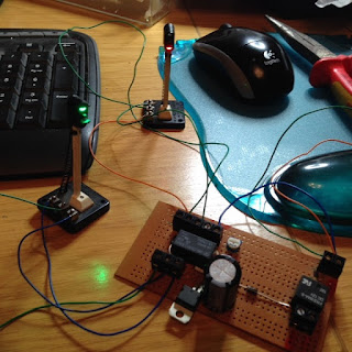
Next came the dual signal aspect control, based on the same principal as the one installed some months ago at the other end of the station but utilising the power from the points relay to determine which aspect operates through the delay circuit. A video would demonstrate this better but the circuit board is below:
As with all my electrical projects, I bench-tested for correct operation before installing...
It works perfectly and I will capture some video footage of this when the layout is next in use.
Next it was time to install the second semaphore and wire it in sequence with the existing one. Bascially I have a single home signal at one end of the layout with the intention of adding a dual home and distant signal after the TPO, with the distant signal wired to activate with its home signal as the train passes and then the distant signal would return to green once the other home signal has reset (does that make sense?!)
The system for operating a semaphore is different to the colour signals in that we need a pulse power feed rather than a constant power supply. To achieve this I produced a timing circuit with additional capacitors to operate in the same way as the points, ie when power is applied, it travels through the capacitor until charged, which basically means a pulse feed is sent through one coil and when the power is cut, the capacitor discharges through the other coil. This works well on the points and also works well if powering one signal.
However there is one flaw with the design - the ground connection is not wired to the common terminal, it goes on one of the coil connections. With the dual signal there are four feeds and only one common, bascially it means that I can't get the signal to operate using the same circuit.
After more trawling of the internet I managed to find a schematic for a dual capacitor discharge circuit, so I removed the existing one from the board, added the extra capacitors and made the relevant wiring changes. The schematic diagram assumed the use of a DPDT switch, so in theory the relay would operate in the same way, right?
Wrong!
What I had basically just unwittingly constructed, via the 25v 4700uf capacitors was a rather large 25v power supply. The relay coils, being of 12v rating, couldnt cope with the power being sent through the coils and while one survived, the other fried!
So after more head-scratching I realised that what I needed, and what the schematic really should have included, was diodes - two for each charging circuit to stop the voltage feeding back through the relays. After more checking with the multi meter I was able to confirm that the capacitors were then charging properly and thus, the dual signal then operated perfectly, with a nice, positive "clunk". Thankfully my old marshall power supply also survived being back-fed with 25 volts!
The final circuit, while not the prettiest I've ever constructed, is below and will be fitted to the underside of the board shortly...
But the bang and the sparks were pretty impressive!


No comments:
Post a Comment