Monday, 17 March 2014

LED signals

I have amassed a fair collection of colour light signals, sadly most of them don't work because one or both of the bulbs have fused.

Although spare bulbs are readily available, the new layout is being constructed with public exhibition in mind, that means that the signals could be lit for up to or in excess of eight hours at a time. Filament bulbs generate heat and heat discolours the lamps. Of the working signals I have, the colours are pretty poor and they have a tendancy to illuimate half the layout.

The other issue is that I'd like to use my signal matrix control that I bought years ago but could never use as it can't handle the current consumption of filament bulbs.

Having looked at the back of the signals and the method used by HD to install the bulbs, I worked out a way to fit LEDs instead.

This is in no way intended as a "how to" guide, more of a "how I did..."

Heat-shrink tubing, a hot soldering iron and the ability to solder quickly are must haves.

So, I started with a signal with only one functioning bulb...

The light from this is almost yellow in appearance.

The ladder unclips from the body of the signal and pulls away, the wiring that is just tucked into the body can be eased out.

One screw secures the back of the lampholders to the signal...


I also need to make a modification to the wiring in the base. I'll be fitting the ballast resistor between the body of the signal and the common connection.


The 3.5mm LEDs and ballast resistor, only one resistor is required and can be wired either side of the LED.


My signal controller uses permanent live and switched neutral wiring, so the polarity of the LEDs has to be reversed, the common feed is live.

The long tails of the LED are bent down into the signal body, handily the ladder fixing tends to scrape away some of the white paintwork. If it doesn't then a small section can be scraped away. The ladder will hide it!

Then the two legs are soldered into the body...


Heat shrink tubing is a must to insulate the LED connections properly. The existing wires are soldered to their corresponding LED, the heatshrink is then slid right up to the LED and heated with the soldering iron...


The shielded legs are also bent into position and the wires tucked back into the signal body.

The ladder holds all of this in place, the soldered LED bulbs don't appear to need further fixings to keep them in place, the legs are stiff enough to keep them in-situ.


I unscrewed and removed the "earthing" tab that connects the signal body to the "C" connection. This is then cut and the resistor is soldered between the two connections. This is where quick work with a hot iron is essential as the base is plastic...

Time to test...


Cheap and easy mod. Takes about 20 minutes and as the original lampholders have been retained, this could be reverted back to bulbs if needed (which I won't)


Friday, 14 March 2014

New Layout: Progress 14/3/14

The framework all six boards has been completed & end panels (for joining each board together) have been installed.

Catches and dowel pins have arrived.

Big order for electrical components placed (relays, capacitors and breakout pcb's)

Still require MDF for the sides and tops of the boards.

2 x HD tunnel mouths received, one more required for this layout.

Wiring configuration for 37 pin connectors drawn up.

Started writing a schematic diagram for the points control PCB's, started using Visio to write this but gave up and drew everything from scratch using Excel instead.

Some track lifted from the loft layout, this will be cleaned and the best pieces will be used for the front of the layout. Only the best, straightest, flattest track will be used, this will reduced the risk of track shorts, derailments and uncouplings. As the track is going to be ballasted I need to be sure that none of it is going to fail and require removal / replacement.

Also decided that the signals will be converted to LED. I've already experimented with a signal that had two blown bulbs - I have quite a collection of these now. A while ago I ordered a signal matrix control, although it's really designed for mimic displays these things can be used to control LED signals. Dublo bulbs are too powerful but also they generate a fair amount of heat. This is going to be an exhibition layout, the signals will be illuminated for hours, the dublo bulbs don't like that kind of treatment and have a habit of losing their colour so LED is a better option as well as greatly reducing current consumption. I can also use the matrix pcb to automate the signals using the same principle that I used when I built the relay controlled version I'm using on the portable layout.

Golden Fleece completed


£9.50 Golden Fleece body from Ebay.
Spare chassis left over from attempted repairs on Sir Nigel Gresley (wrong colour wheels)
Tender left over from Silver King.
Armature found in the spares box, tested & working.
New neo magnet fitted.
Connecting rods straightened (catching on one side)
Light oil.
Commuator cleaned up.
Top & bottom motor bearings lubed.
Pick up spoons polished.

In all, about 30 minutes work. Just need to find a securing nut for the body. Runs well, current draw is pretty good...


A nice, cheap addition to the collection that's worth way more than I spent in total. I really enjoy projects like this, making something good out of scrap parts.

Monday, 10 March 2014

£10 Golden Fleece

Well £9.50 plus postage.

Saw this on eBay and couldn't resist. I should have enough spare parts scattered around to make this into a running loco, again this will be a loco that's built entirely from scrap parts. The body is a little play-worn but certainly usable as it is without the need to repaint.

Ages ago I sourced a scrap chassis which was bought to restore Sir Nigel Gresley but when it arrived it had black wheels rather than the Gresley red ones, so I kept it to one side just in case.

My original Silver King was mis-matched with a gloss body and Matt tender so a replacement body and tender was sourced a while back. The old tender I kept to one side just in case.

So all I need to do is find an armature and a neo magnet, then I can turn this into a runner...


Saturday, 8 March 2014

New layout: progress

Made my second run today to purchase timber for the skeleton framework of the new boards. Thankfully my brother, being a demon at carpentry, has already turned the timber I purchased last weekend into the three frames for the front boards.

There will be six boards in total, each will be separate, no hinging this time, the framework will be clad in either mdf or plywood, this should stop the boards from warping like the current ones are prone to.

The layout will be 16ft x 5 ft the outer boards will be 5ft 6 in length, with the centre boards being 5ft each. They should just about fit in the car, they will also be designed to be stacked, the cladding will prevent the boards being stacked on the tracks (another problem with the current layout) and consideration is needed with the height of the scenery and raised track. If it's too high then I'll struggle to transport them.

One of the primary reasons for hinging the current boards was that it reduced the amount of wiring between boards. I need a system whereby the boards will join together with the minimum of wiring. Seeing connections and wires underneath isn't pretty. I've previously used db25 connectors when I first designed the boards (old parallel printer terminals) and these worked relatively well. However although my soldering technique is reasonable, I'll need more terminals. Actually I've worked out that I need 37 pin connectors between the front three boards to allow for all the electrics planned. Thankfully after many hours of searching, I've located some 37 pin breakout pcb's.


These are basically 37pin male and female plugs that are pre-soldered to a pcb board, with terminal blocks for all 37 connections. This will make the whole process much easier to wire. I plan to have the connectors mounted on the board joins along with dowel pins, when everything is lined up, it'll be a simple job to just clip the boards together - no wires, no fuss. That's the plan anyway.

I was originally going to use standard 12v automotive relays under the boards, problem is these are large and will look untidy so I've worked out that I can make three separate points control pcb's (one for each board) and make a separate pcb for the track isolators.

I've already spent some time mapping out the configuration of the 37pin connectors - having everything written down is a novelty for me, previously I keep it all in my head but electrically this project will have much more electronics than the current boards have,  also to reduce the volume of wiring from the switch panel (which I also need t build) I will need to use remote relay control.

After many hours trawling the internet for a suitable enclosure for a control panel, I've decided that they're far too expensive, better for me to construct my own from scratch. I've seen many fine examples of DIY built panels, I know in my mind how I want mine to look. I'll be abandoning the A3 controllers for the main lines but will retain one for shunting duties on the back boards. Ideally I'd like to use Gaugemaster controls as these can be supplied in panel mount format. I've also located a suitable track shuttle device that can also operate two signals. I'll build a manual override control using a relay pcb.

Lots and lots of work to do and lots of money to be spent. The deadline is November, for now the existing track on the portable layout will be left alone so that it can still be used. I think we'll leave that part right until the end if we can and get the wiring, connectors, dowel pins and latches fitted
first.

This is going to be a mammoth project, without doubt the biggest challenge to my wiring skills yet. If it all comes together as planned it'll look fantastic...

...I hope.


Monday, 3 March 2014

New layout: First Steps


And so it begins...

After my initial design using SCARM, it was decided that we'd try a mock-up of the track work for the front of the layout. This simply involved loose-laying the tracks across the tables, I grabbed a pile of spare track (sadly not enough points) and masking tape to illustrate the size of the boards and where the joins would be, so that point work and crossovers could be moved if needed.


16ft x 5ft approximately. The front section will incorporate the main station and level crossing as it does now, along with the turntable and a small terminus at the other end.


Masking up showed me where the board joins would be and what track work needed to be moved.


The raised section is also loose laid, for now just placed over the existing tracks so that we could see where bridges and tunnels would be needed.


Saturday, 1 March 2014

The new layout begins...

After much deliberation, I'm going to have a go at a totally new portable layout.

The design I put together using SCARM has been mocked-up using loose track laid on tables, with sections masked off to indicate where the board joins would be. On the face of it, it should go together reasonably well but will require completely new boards. I've purchased some of the timber required so that work can commence shortly. The absolute deadline to get this layout in show able condition is November. That sounds like ages away but in reality there's a lot of work to be done.

It's been agreed that we will incorporate a raised loop but this will be a single line section, there isn't really sufficient space to make it double track. The village terminus idea will fit as planned and I can also use this to run a shuttle DMU (or EMU) between the stations. Basically I'll have three running loops and an end-to-end terminus, plus any shunting or turntable moves. Whilst the new layout will be shorter, there will be more going on and with so much rolling stock it'll double the amount of running items. I also like the idea of having tunnels and bridges, and of course the ability to leave platforms, signals and TPO apparatus in-situ. This will significantly speed up the time taken to set up which means more time to run the layout! There will also be a significant amount of wiring involved, thankfully having done the loose mock up today I can work out roughly what wiring is needed, relays, capacitors etc and start building any control circuits etc.

The new layout, when finished, should tick all of the items below:

Faster setup with more fixed track
Platforms can be fixed into position
Platforms and buildings can be illuminated
Signals fixed in position and permanently wired
TPO fixed into position and permanently wired
Raised track, independent of the two loops
End-to-end terminus running
Ability to run four trains plus shunting duties
Use of tunnels, bridges and scenery
Reinforced boards that won't warp in storage
Increased siding space at rear of layout
One person operation more practical (standing behind layout, not inside it)
Self-supporting legs, not running on tables
Able to use the Märklin turntable

If I've ticked all these by the end of the build, I'll be happy.

Friday, 28 February 2014

Turning the turntable part 2

The paint's dry and the glue has gone off.

Had to ream out more of the centre section of the girder so that it cleared the electrical contacts in the centre.

After some reassembly...

I started with this...

I wanted it to look more like this...


And this is the final result...


Close up of the motor house. I could have made a better job of the paintwork but I'm happy with the final results. The girder section here had to be halved in thickness to fit in the space available. I could have repainted the original fences but they weren't in great shape and besides, I really wanted the Dublo girders if I could.


Just a small bit of rewiring needed underneath. I also plan to remove the four connection pins on the side, as the turntable will need to be recessed into the new boards (due to the difference in track thickness between Dublo & Märklin track) the holes where the pins used to be wont be visible.I can then connect it up to my modifed controller that I built a while ago.

The grey paintwork is in good condition overall and I don't currently have a suitable match for the original Dublo colour. Removing all those tracks on the edges is going to be the only way that I can really get a decent paint finish, I don't think that just masking the tracks would give a good enough finish. So for now the existing grey paintwork is staying.

I'm sure there will be some that will scoff at what I've done to this, I think it's interesting and shows what you can do with a reaming tool, a bit of paint and a heck of a lot of time.


Thursday, 27 February 2014

Turning the turntable part 1

I like my Dublo turntable. I don't like having to turn it by hand, plus if the planned changes to the portable layout go ahead it'll be hard to reach.

It could be motorised - there are videos on YouTube that prove this, and for use in the loft that would be fine as the gearbox and motor assembly needed are quite large in size and really not suited to portable operation. Then there's the little issue automatic indexing, again it can be done but time, money etc...

I like my Marklin turntable also. But I don't like the colour or the general way it looks, it's quite bland really and if I added it to the portable layout it would stick out a country mile that it's not a Dublo item. However the self-contained motor and indexing system work really well.

If only I could make this...


Look like this...


Time for a project.

I had a broken Dublo turntable, my plan is to take the girder supports and graft them onto the Märklin turntable and repaint it.

First of all, I had to strip both turntables. The Dublo one, well the only thing that holds the centre in place is the track work so this prised apart pretty easily, followed closely by the two girders.

Now to strip the Märklin one clip and the rotating section lifted away. The small building I already knew would just unscrew and lift off. The electrical contacts in the centre of the turntable could then be disconnected and removed.


Time for some rubbing down and priming...


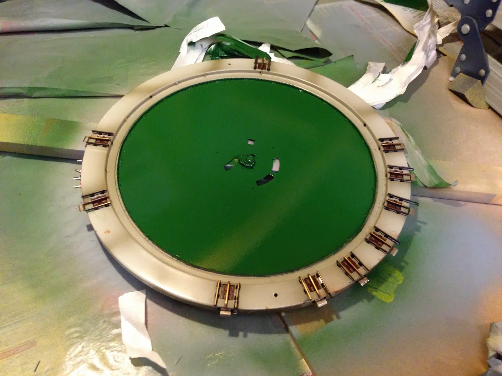
I decided to spray the centre, within the large outer cog green to match the old Dublo one. The grey, although a different shade, I will leave for now. To paint the rest properly would involve removing all the track sections, this increases the risk of damage so it's just not worth the risk.


Time to paint the building in traditional Hornby Dublo colours (more sahara beige!)


Happy with the results after removing the masking tape


Once the beige was dry, time to give the roof a coat of red to match my other Dublo buildings.


The centre section I was originally going to leave grey but after a while I decided to repaint this also. This meant removing the motor assembly, the latching mechanism, drive shaft and guide wheels. By now they've been primed and painted green, with the Märklin railings removed.


Lots of work required to get the girders to fit, both have been reamed substantially to fit.
There are electrical contacts in the centre which foul the girder in the foreground, so the inside has been reamed in the middle.

For the rear one, it's been reamed around the building as the two wouldn't fit together, there wouldn't have been enough room to get the train through!

Couldn't resist a quick mock-up having spent so long doing this. Next stage is to fix everything back in place and fit this back into the body of the turntable.


More to follow...


Sunday, 23 February 2014

New layout (possibly)

The loft layout isn't making much progress - every time I run the portable layout I seem to need to steal bits from the loft layout, which then take ages to be replaced.

Then there's the portable layout - love it. It's huge, actually it's too huge for one person to operate. You stand in the middle which means you can't see what's going on behind you, so you turn around to check, then something happens on the other side. It's too big for many of the exhibition opportunities so it's likely to get used barely two times per year. Then there's the design - I'd like a run around loop. I have one in the loft, I need one on the portable layout. I'd like the boards redesigned so that I could include some scenery, nothing too major but with the right design I could leave the signals and stations in-situ, even the TPO. Then if we add hills and raised sections, why not add a raised third and fourth loop? - four train running! Makes more sense with so much rolling stock sitting idle. And maybe a small village terminus so that I can run round locos etc.

After much thought and debate, I took to SCARM again one evening. I'm still not overly expert at this thing  but managed to mock up a suitable 16ft x 5ft layout - same length as the current on but narrower. I can stand behind the layout and watch the whole thing...


The bone shaped track is how I envisage a raised section looking. Currently only one loop but potentially there would be a second.

This is only the first draft but already this design would give me much more siding storage than I have at present, with the potential of up to four trains running, plus a small terminus station and a run round loop. The beauty of three rail is that there are no polarity issues to worry about as the centre rail is constantly live.

Just need to work out the costs, I have the track but the boards will need to be custom made.

Time to start saving...

Monday, 17 February 2014

80059 arrives

Sadly too late for a decent weekend run but I'm now a proud owner of one of the rarer Dublo locos.

80059 was only in production towards the end of Hornby Dublo production and decent examples are rare, and costly.

This one is a little play worn but that's fine, I didn't want a pristine boxed example, it's going to get used. A quick spin around the loft tracks showed no mechanical issues at all, it's one of the fastest locos I have and clearly there's plenty of strength in the magnet.

A welcome addition.


Thursday, 13 February 2014

80059

Finally, after many months, even years of bidding, being outbid, bidding again only to lose out in the dying seconds, going to toy fairs and forgetting the cheque book, going to toy fairs and finding pristine ones only to lift them up and find its a two rail version... I landed myself an 80059.

Sadly it probably won't arrive in time for the weekend but this is one of the locos that I really, really wanted in my collection. I've gone with my tradition of buying an unboxed example, I have no need for boxes, it would have spent more time out of a box than in one and I can't wait to get my hands on it.

That's another one to cross off the wish list, once the bank balance recovers I'll start searching for a nice St Paddy!

Pictures to follow, once it's arrived. :-)

Triple headed Deltic!

The green Deltic, with its o ring shaped tyres, has always caused me grief, especially over points so I ordered some more Märklin tyres, which arrived today and were fitted shortly afterwards.

After a few concerning sparks flew out of the cab windows, it settled down and ran sweetly, drawing around 0.4 amps.

I then tried double heading with Crepello - I know that Crepello and Royal Scots Grey work well together after their performance during the last two runs on the portable layout and the two ran very sweetly together and appear well matched power wise. Current draw stabilised around 0.75 amps.

So I had to experiment. And this isn't something that I'd try with an A3 controller but as I have a spare H&M which I use in the loft for the sidings, I had to give it a go... Could I really get three of them to run together? Would they stay together? Would they run at all?


The answer is yes!!!

Pushing the limits of the controller I think and no doubt once coaches are attached, the rolling resistance will increase the current draw. 


They ran together perfectly, no uncoupling, no derailments, no overheating.

I don't think an A3 controller would handle it though!


Wednesday, 12 February 2014

Final tweaks

The roofs are all now dry and have been properly attached to the mail sorting coach and breakdown crew coaches. I decided to have a bash at repainting the roof of one of the mail coaches due to the amount of rust. Unfortunately the mail coach roof doesn't detach like the others so I had to mask off the whole coach, being careful to avoid overspray.

Thankfully the results aren't that bad.


Finally before all the new additions get boxed up ready for the weekend, there's this little gem...


It's a repaint with new transfers and it looks stunning. Way better than anything I could hope to produce! My original plan was to put this aside until a suitable scrap chassis turned up at a reasonable price but when I saw it I thought it was too good to leave on the shelf. Having inspected my two original black 2-6-4 locos, 80033 is the one that looks the worst, so I've temporarily swapped the bodies over. I may attempt a full repaint and re-transfer of 80033 now that I have more confidence with this kind of work. If my results are anywhere near as good as this one then I'll do 80054 too. 

I seem to be developing a tank fetish. There's something about 2-6-4s, I'm not a steam buff - maybe it's because I had one of these as a kid and realised then how indestructible they were. Ours ended up being jumped off a made up three rail ramp! They're easy to work on, they run well and give very little trouble even when double heading and they sound really sweet.

I'm still on the lookout for the highly desirable and very rare 80059. It's eluded me many times now, I've probably bid on more of these than any other loco and lost every time. The last one fetched almost £300. It was pristine and boxed, which kind of broke my own rules but just too much money.

If and when I do finally get my hands on one, if it needs repainting then it'll get sent away for a professional job.

For now though all the remedial work I'd planned, including the emergency board repairs, are complete. There's a substantial amount of track work fixed in place and cut to size, which will speed up the setup process. I'll investigate fixing more tracks on the day.

Tuesday, 11 February 2014

Transfers

I've had these for ages.

I made a Royal Mail sorting coach a while ago using transfers supplied by eBay seller lhp media.

I used the same supplier for the recent restoration of the 0-6-2 tank engine and after some tidying of my office, I found the other transfer sets that I'd bought and subsequently lost.

These are fitted to some of my less-pretty Dublo tinplate coaches, all of the coaches used had either rusty roofs or damaged paint.

The roofs were removed and painted with halfords grey primer, with two coats of clear lacquer to make them shine. After the sides of the coaches were given a light sanding, the transfers were applied. I then added a coat of lacquer to these to add more shine but this has to be done carefully due to the design of the transfers.

So after very little effort, I now have another Royal Mail sorting coach to add to the mail train and two coaches to add to the breakdown crane. More importantly, four rusty and play worn coaches that would have never seen any use have been salvaged and will have prominent positions on my layout.


The roof of the final breakdown crew coach is still drying!


Monday, 10 February 2014

Storm damage

It's been raining a bit recently...

Thankfully no major flooding round these parts, however I do store the boards of the portable layout at the back of my garage. Mindful of the fact that the garage is only single-skin brick and southwesterly facing, I keep the boards stacked off the floor and away from the rear wall.

BUT... The rear section must have fallen against the rear of the garage and when I checked it earlier today, one section was soaking wet and mouldy.

I had intended to carry out some remedial work to this board by cutting and wiring the tracks together like I've done with one of the other hinged boards. The idea being to make it quicker to set the layout up and pack down without having to remove so much loose-laid track.

Although I'd planned to eventually upgrade this section of the layout, I don't have the time, money or enthusiasm to have this completed by this weekend. I tried to chisel out the blown section in an attempt to get the tracks to level out but in the end I realised that I was wasting my time.


Thankfully I found a near-identical piece of MDF in the loft...


So the damaged piece was unscrewed & removed and the replacement slotted in. I also managed to find a scrap piece of grass mat and after some more searching I found the PVA glue...


Time to relay the track. I had experimented with this section previously with fixing all the track down but had never trimmed the track to size, leaving a big overhang of track on one side when folded up, which then got bent and eventually snapped off.

I had envisaged having to cut the tracks level with the ends of the hinged sections but after some tweaking with the 1/4 sections of track that were already on the board, I managed to get the two ends close enough to the edge to avoid further cutting.

After a quick solder job underneath, the tracks were screwed back down...


At the moment, the tracks line up perfectly without the need for adding cut-down fishplates. I'll keep some in reserve just in case I need some at the weekend.

A brief run over both sections using my recently acquired brick wagons confirmed that both sections were fine...


I'll leave this section indoors to let the glue dry properly. The rest of the boards look to be ok but I guess I'll only know for sure when they're all set up on Saturday.

Fingers crossed.


Saturday, 8 February 2014

Early attempts at three railing


You have to break a few eggs to make a good omelette.

Here are a few of the "eggs" from my first attempts...


Dapol class 155

I travelled on these during their very brief appearance before being sent for conversion into 153s and wanted one for the layout. Sadly there isn't really enough room under the bogies for a proper skate so flattened brass paper fasteners were used. It didn't really work and while it will still run in a straight line, it doesn't do points or corners due to the down-force exerted by the pick-ups. Maybe one day I'll get it running.


Lima class 33

I wanted a 33/1 due to my Southern region upbringing and this is the closest I've got so far.

Again clearance underneath was an issue, this has two small copper strips that were originally the two rail pick-ups from a hornby pacer. It runs but won't pull much more than its own weight. Possibly can be resolved by adding ballast.


Class 142 Pacer

The only three rail pacer in existence? - ironic really considering that in real life these things are banned from third rail areas!

My first three rail attempt of modern-ish stock. Bought cheap on eBay with broken couplings. These two carriages are joined together by connecting wires with a single Castle class plunger at each end. Although the springiness of the plungers reduces the downward force, this actually runs quite well and was used a fair bit on the portable layout when I first built it and had very little running stock. 

These days it's hardly used and I couldn't bring myself to exhibit this in public!


HST

Just about runs but won't pull more than three coaches. Another conversion using brass paper fasteners and there isn't much clearance under the bogies. Fine on track without too many points, so doesn't get much use now.


Thursday, 6 February 2014

Finished!

The front coupling for my 0-6-2 tank project arrived today, so I wasted no time in heading for the loft to attach it to the loco...


It ran without fault and happily keeps up with the other tank engines, which is handy for double heading. Admittedly it's very glossy and the red paint on the buffers could have been done better but for someone with zero artistic skills I'm really happy with how this turned out. I don't have the heart to sell it so once again I'm adding to my existing collection!

Monday, 3 February 2014

Minor mishap

My smugness and self-satisfaction levels after the repainting the 0-6-2 tank were very short-lived!

After checking the pictures that I'd uploaded I decided to go back and repaint the buffers again... Big mistake!

Sadly as I took the brush from the pot of red touch-up paint, it dripped... right on top of the roof of my lovely, newly painted loco. And of course the lacquer coat was still a bit tacky so this got ruined!

Thankfully it didn't land on the stripes and I was able to rub down and repaint the cab roof and re-lacquer. All is now well.

I also finally got around to sorting out Dorchester. I decided to fit a brand new set of brushes, this cured the problem as there was no visible sign of any issues with the brush springs. Both locos run happily along the test track in the loft and they'll get a proper run-in next weekend. Hopefully by then I'll also have sourced a new front coupling for the tank engine...


Sunday, 2 February 2014

My first go at repainting a loco


I have loads of 0-6-2 tank engines and really didn't need any more, I have reasonable examples of the two most common versions and acquired several repainted bodies, which I've combined with refurbished chassis over the years.

One of the things I've never attempted is a loco repaint. Now it's fair to say that my talents really lie in the mechanical side of things rather than cosmetic but with a fair collection of scrap loco bodies piling up, and the recent acquisition of two more, rather sick looking 0-6-2 tanks (and the 2-6-4 that I already restored with a replacement body) I decided to have a go at repainting.

The loco body had been stripped a while ago when I did the platforms using an overnight soak in oven cleaner.


After a soak and rinse, I ended up with a stripped body.


The body was then primed using halfords grey primer, then it got left for months!


Having finally found some enthusiasm to finish what I'd started, I then applied two coats of black.


After being left to dry, it was time to apply the transfers. These were sourced from eBay about three years ago from lhp media. They arrive on a sheet and require cutting out and applying.


And this is the finished result, I added lacquer to give the loco a nice glossy finish, also because there was a notable difference between the finish of the loco paintwork and the finish on the transfers. Finally the red inserts were painted in front and rear.

It will be reunited with its chassis, which has already been restored, just need a new front coupling and screw as these were missing.

I can't say that this is something I'd consider doing much of and the idea of restoring something like a duchess or A4 body is something that I think is still way beyond my abilities, but I'm happy with my first attempt and it's nice to see another loco that would potentially have been scrapped saved from this fate.